Palfinger Loader Cranes
Notice: Undefined variable: out in /mnt/wordpress_data/fo.kj/wp-content/themes/twentyseventeen-child/template_palfinger.php on line 281
PK 88002 EH High Performance
The Power Link Plus enables operations within confined spaces.
- High value retention thanks to coating technology
- Additional applications due to Power Link Plus
- Maximum utilisation of the working range due to HPSC
- More lifting power due to E-HPLS
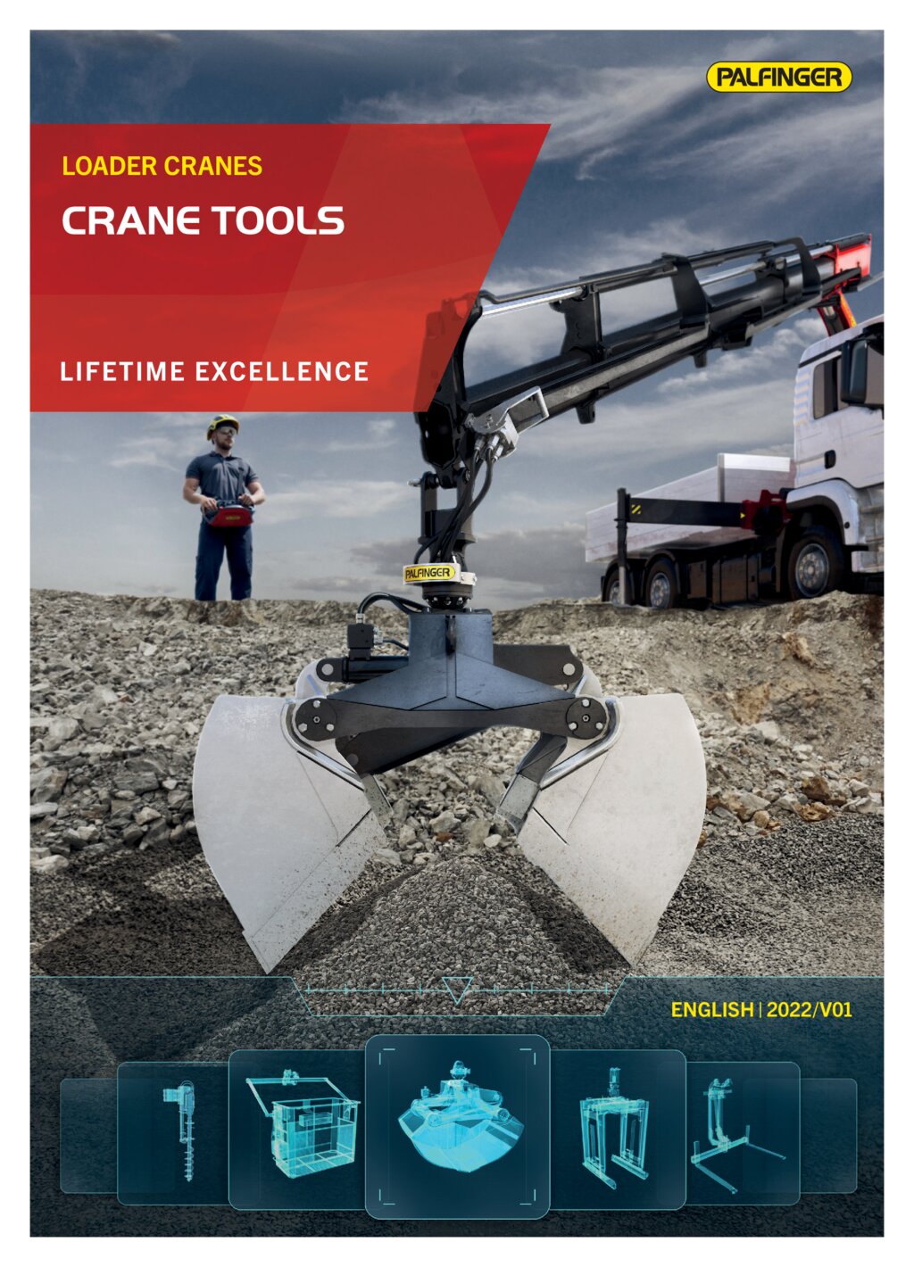
Brochures
PK 88002 EH

| Max. lifting moment | 81.6 |
| Max. lifting capacity | 30000 |
| Max. hydraulic outreach | 22.5 |
| Max. manual outreach | 25.0 |
| Slewing angle | ∞ |
| Slewing torque with 2 gears | 7.7 |
| Stabilizer spread (std) | 8.6 m |
| Fitting space required (std) | 1.92 |
| Max. operating pressure | 365 |
| Pump capacity | 110 - 130 l/min |
| Dead weight (std.) | 6780 |
Cranes shown in the leaflet are partially optional equipped and do not always correspond to the standard version.
Country-specific regulations must be observed. Dimensions may vary. Subject to technical changes, errors and translation mistakes.
Country-specific regulations must be observed. Dimensions may vary. Subject to technical changes, errors and translation mistakes.
Lifting moment | Outreach | Slewing angle | Slewing torque (mt) | Pressure | Pump capacity (l/min) | Crane Weight | Crane Height | Crane Width | Installation Width | Max stroke lenght | Max lifting capacity | Load vertical | |
|---|---|---|---|---|---|---|---|---|---|---|---|---|---|
| A | 78.8 mt | 7.4 m | ∞ | 7.7 | 36.5 Mpa | 110-130 | 6780 kg | 2470 mm | 2550 mm | 1645 mm | 7266.45 mm | 30000 kg | 11100 kg |
| B | 77.7 mt | 9.3 m | ∞ | 7.7 | 36.5 Mpa | 110-130 | 7140 kg | 2470 mm | 2550 mm | 1645 mm | 9130.45 mm | 29800 kg | 8600 kg |
| C | 76.8 mt | 11.3 m | ∞ | 7.7 | 36.5 Mpa | 110-130 | 7505 kg | 2470 mm | 2550 mm | 1645 mm | 11149.45 mm | 29000 kg | 6800 kg |
| D | 75.9 mt | 13.5 m | ∞ | 7.7 | 36.5 Mpa | 110-130 | 7849 kg | 2470 mm | 2550 mm | 1645 mm | 13334.45 mm | 27800 kg | 5400 kg |
| E | 75.0 mt | 15.7 m | ∞ | 7.7 | 36.5 Mpa | 110-130 | 8180 kg | 2470 mm | 2550 mm | 1745 mm | 15544.45 mm | 27200 kg | 4350 kg |
| F | 74.1 mt | 18.0 m | ∞ | 7.7 | 36.5 Mpa | 110-130 | 8479 kg | 2470 mm | 2550 mm | 1790 mm | 17800 mm | 26000 kg | 3550 kg |
| G | 73.3 mt | 20.2 m | ∞ | 7.7 | 36.5 Mpa | 110-130 | 8736 kg | 2470 mm | 2550 mm | 1795 mm | 20073.45 mm | 25500 kg | 2950 kg |
| H | 72.9 mt | 22.5 m | ∞ | 7.7 | 36.5 Mpa | 110-130 | 8923 kg | 2470 mm | 2550 mm | 1795 mm | 22397.45 mm | 24700 kg | 2450 kg |
The outreaches stated are with a boom angle of 20° and are therefore not the maximum. When using mechanical boom extensions, the loads shown on the charts need to be reduced by the weight of these extensions.